ABS METHOD
OVERVIEW OF AIR-BAG STOPPER METHOD
The Air-Bag Stopper Method (ABS Method) is a simple method developed for temporarily shutting down water pipeline by inserting an inflated air-bag through a drilled pipe via a saddle.
The ABS Method enables shutting down water pipeline at minimal section within a short time of period. The method also enables water suspension-free construction to carry out through a whole pipeline construction series, rather than individually separating construction phases.
There are two types of approaches for applying ABS Method, depending on the saddles;
Method Type 1/With a self-developed stopper-saddle made specifically for ABS Method
Method Type 2/With commercially available ferrule with a saddle
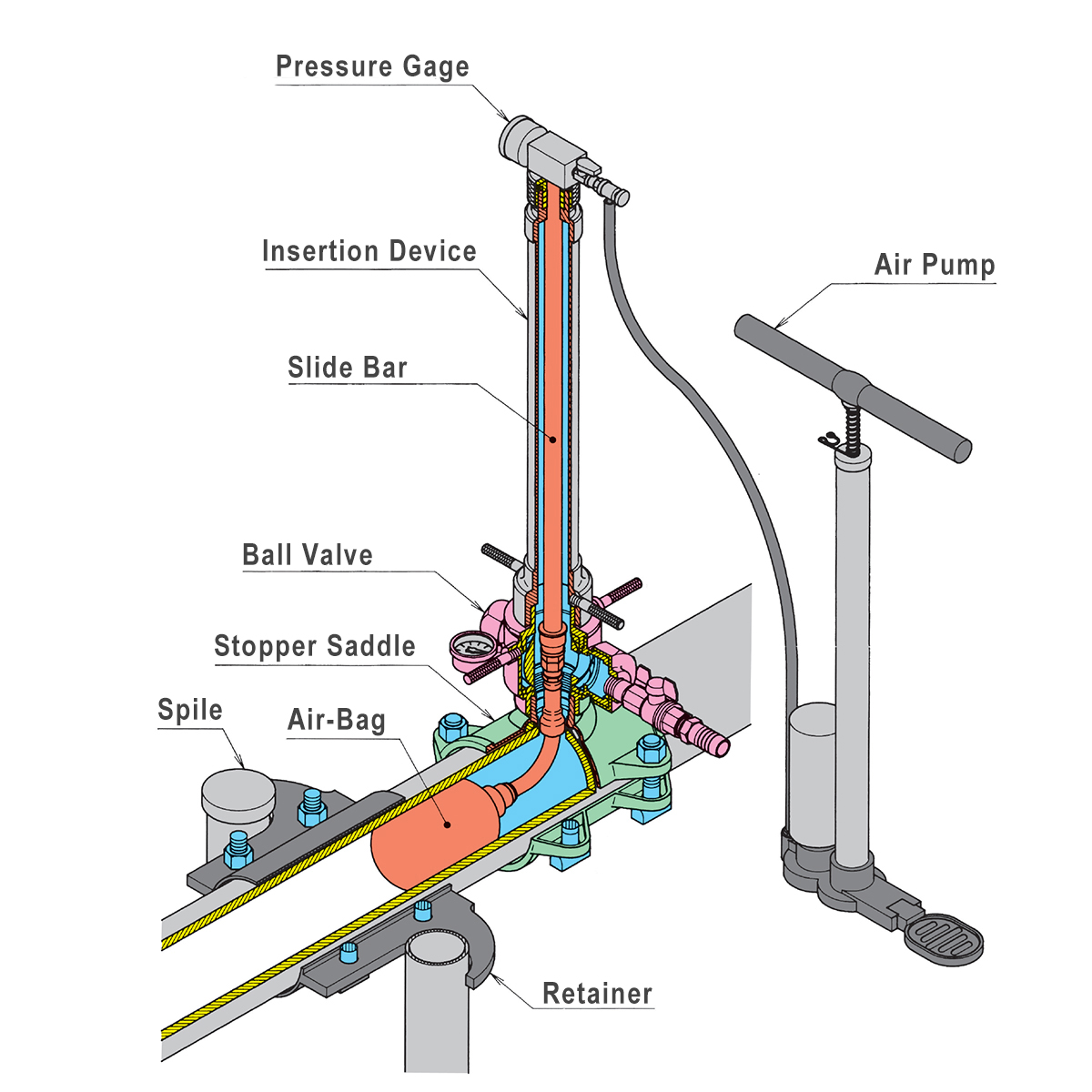
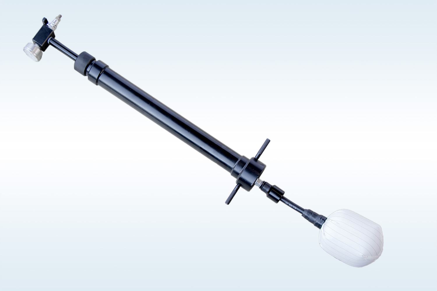
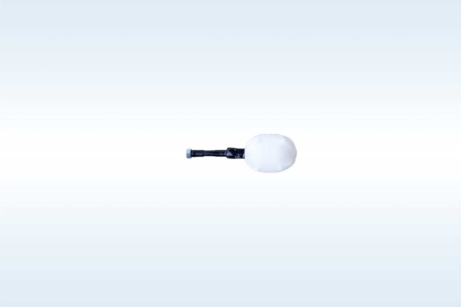
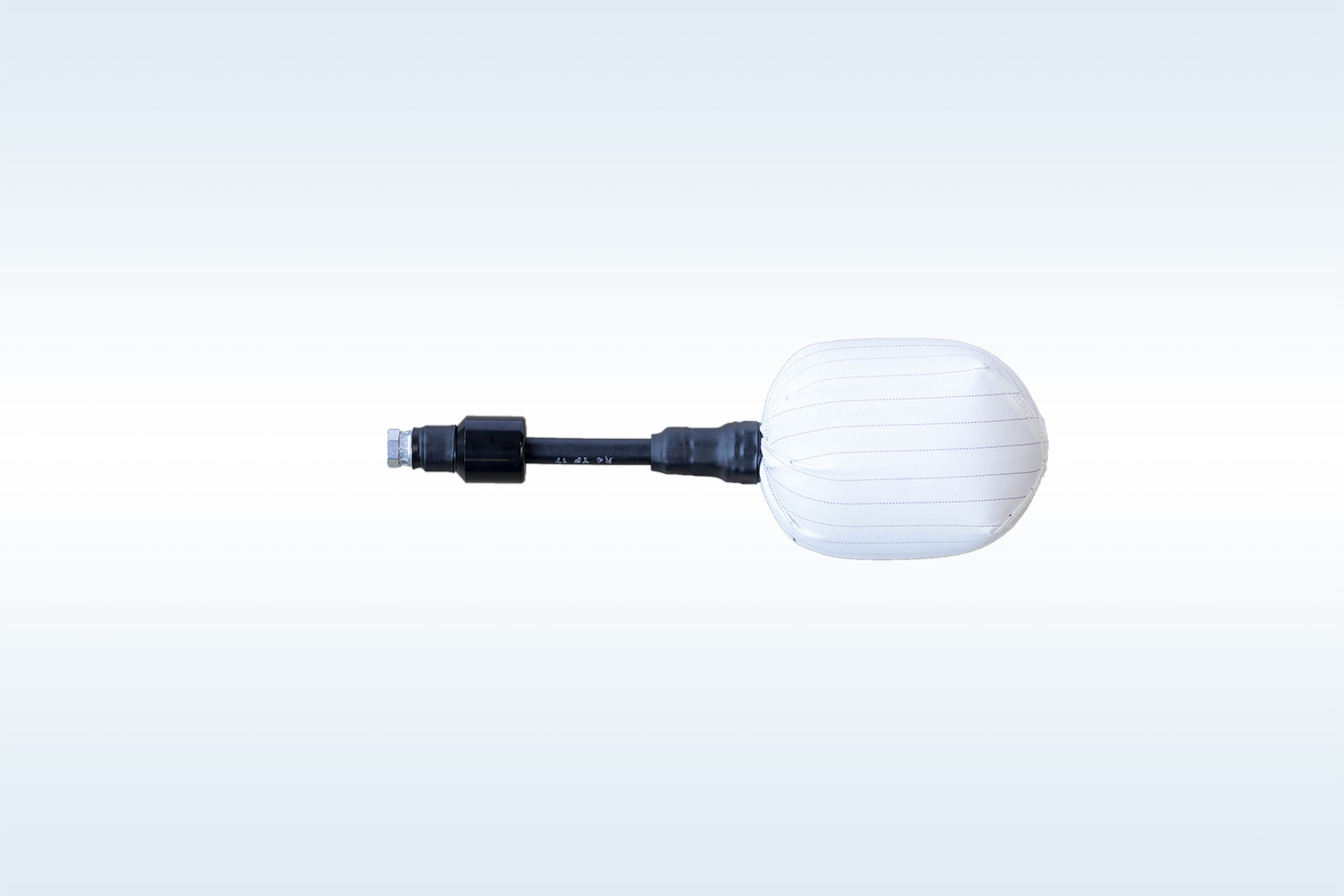
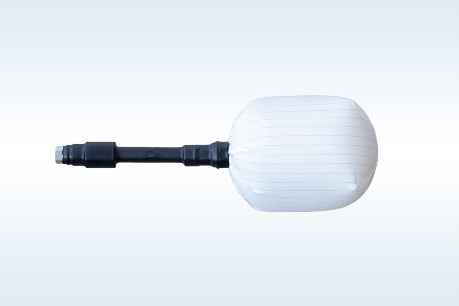
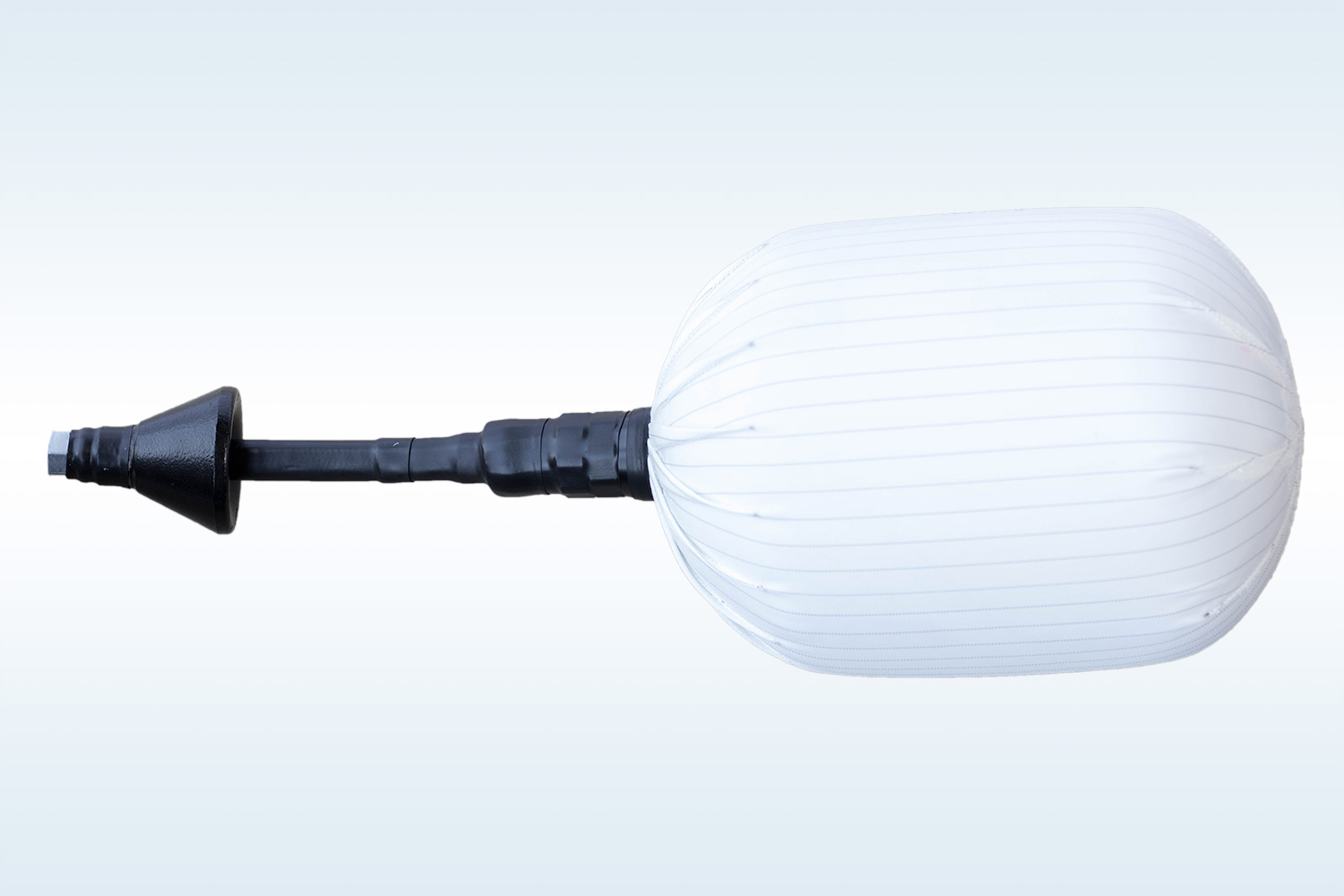
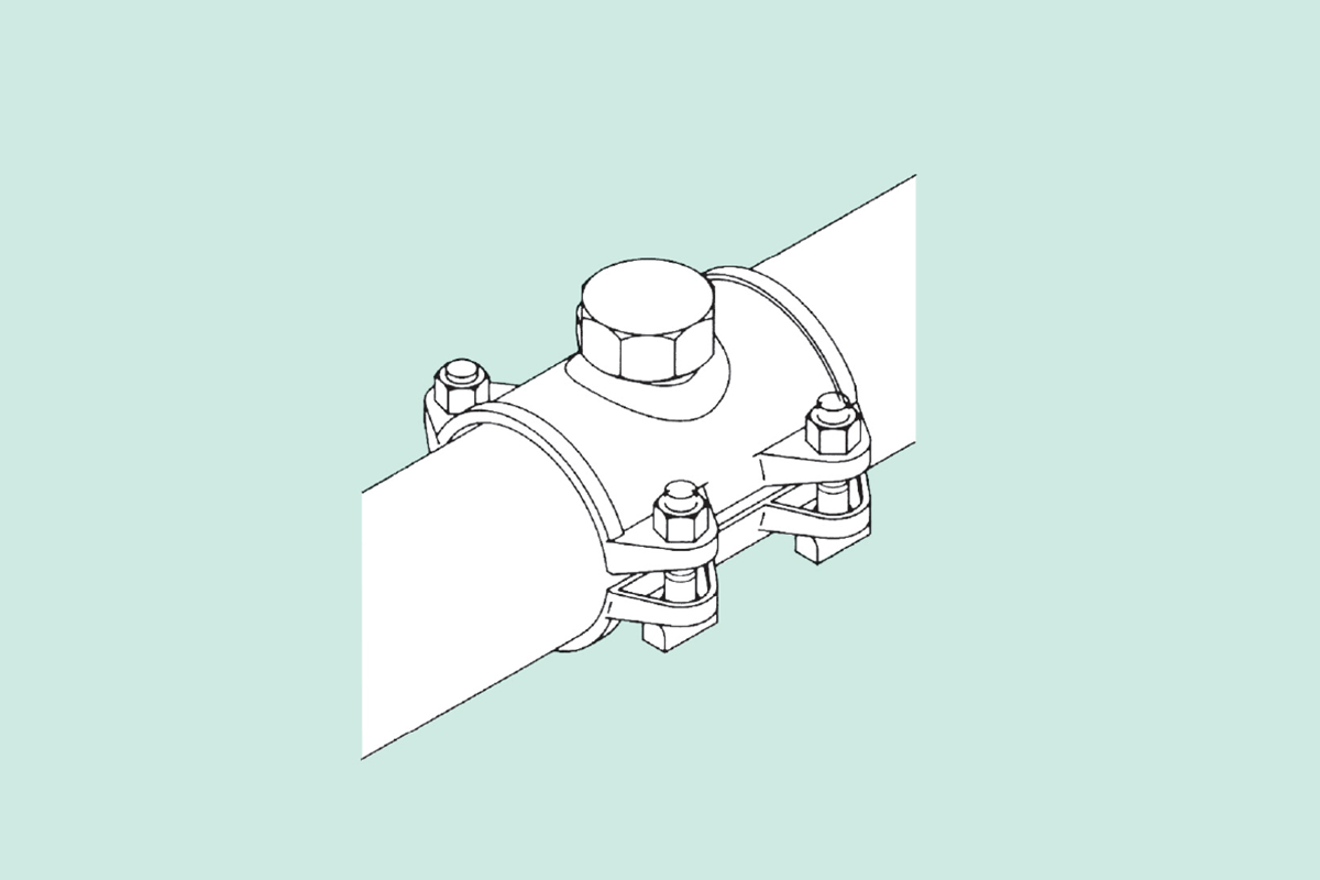
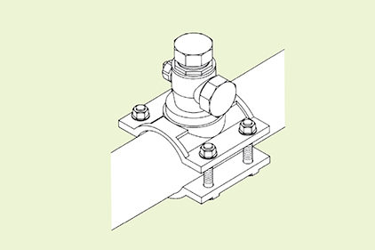
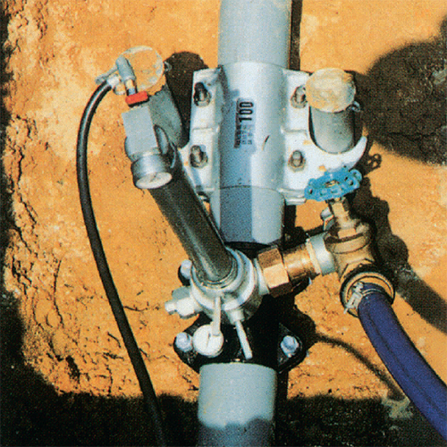
Component Image for Method Type 1
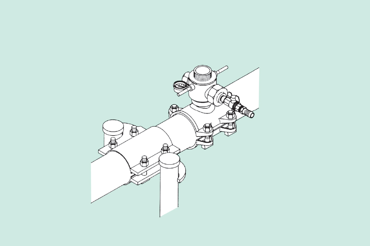
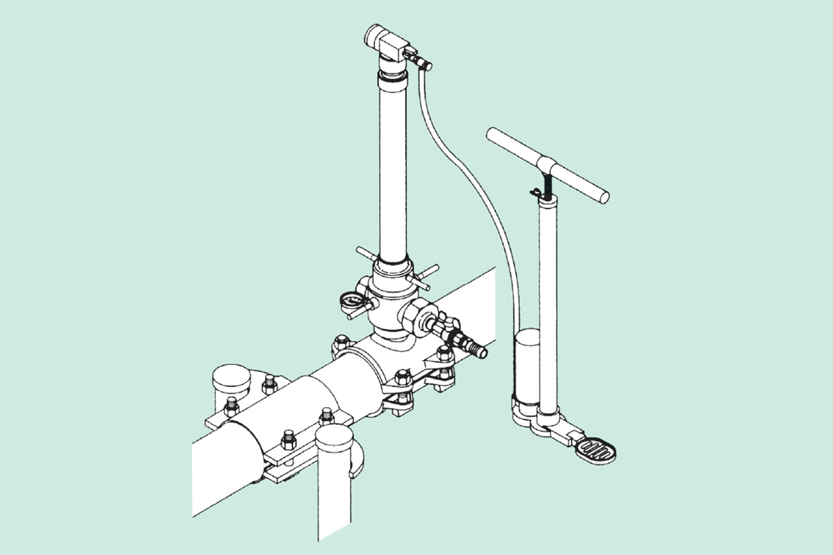
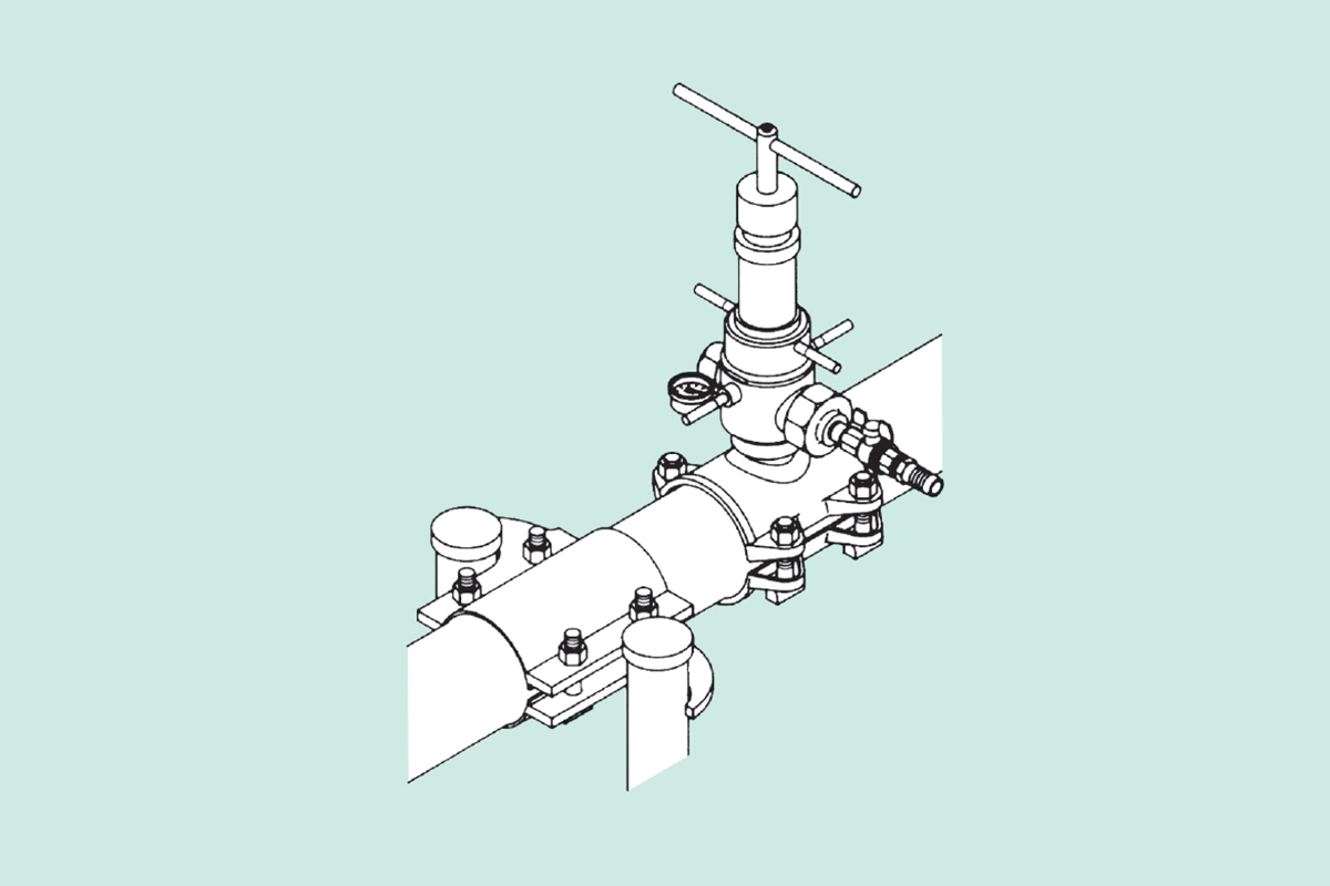
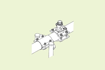
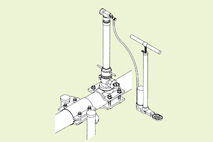
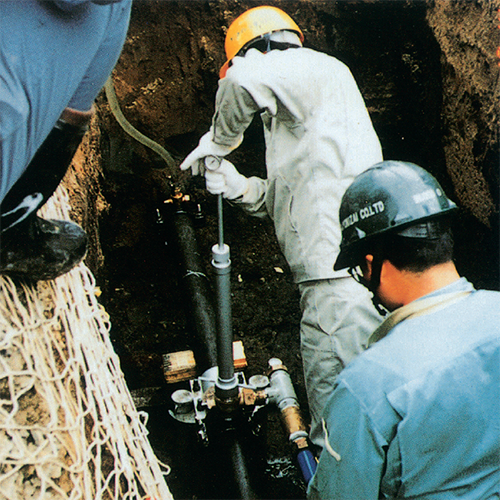
PROCEDURE
ABS CONSTRUCTION PROCEDURE
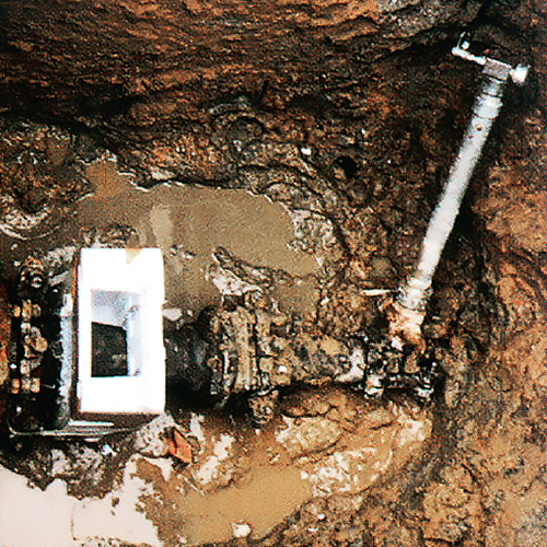
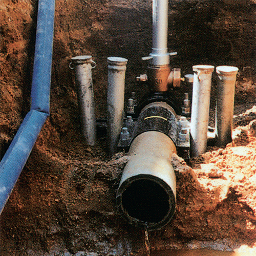
EXAMPLE WORKS
CONSTRUCTION SITES ABS METHOD WAS APPLIED
-
T-City・φ100 ductile iron pipe
PIPE LEAKAGE REPAIR
-
K-Town・φ125 ACP
PIPELINE RENEWAL
-
M-City・φ100 PVC pipe
GATE VALVE REPLACEMENT
-
T-City・φ100 ductile iron pipe
DISASTER RESORATION
-
K-CITY・φ6″ ductile iron pipe
PIPELINE RELOCATION
-
S-City・φ100 ductile iron pipe
PIPE RELOCATION
INTRODUCTORY MOVIE
AN INTRODUCTION MOVIE OF ABS METHOD
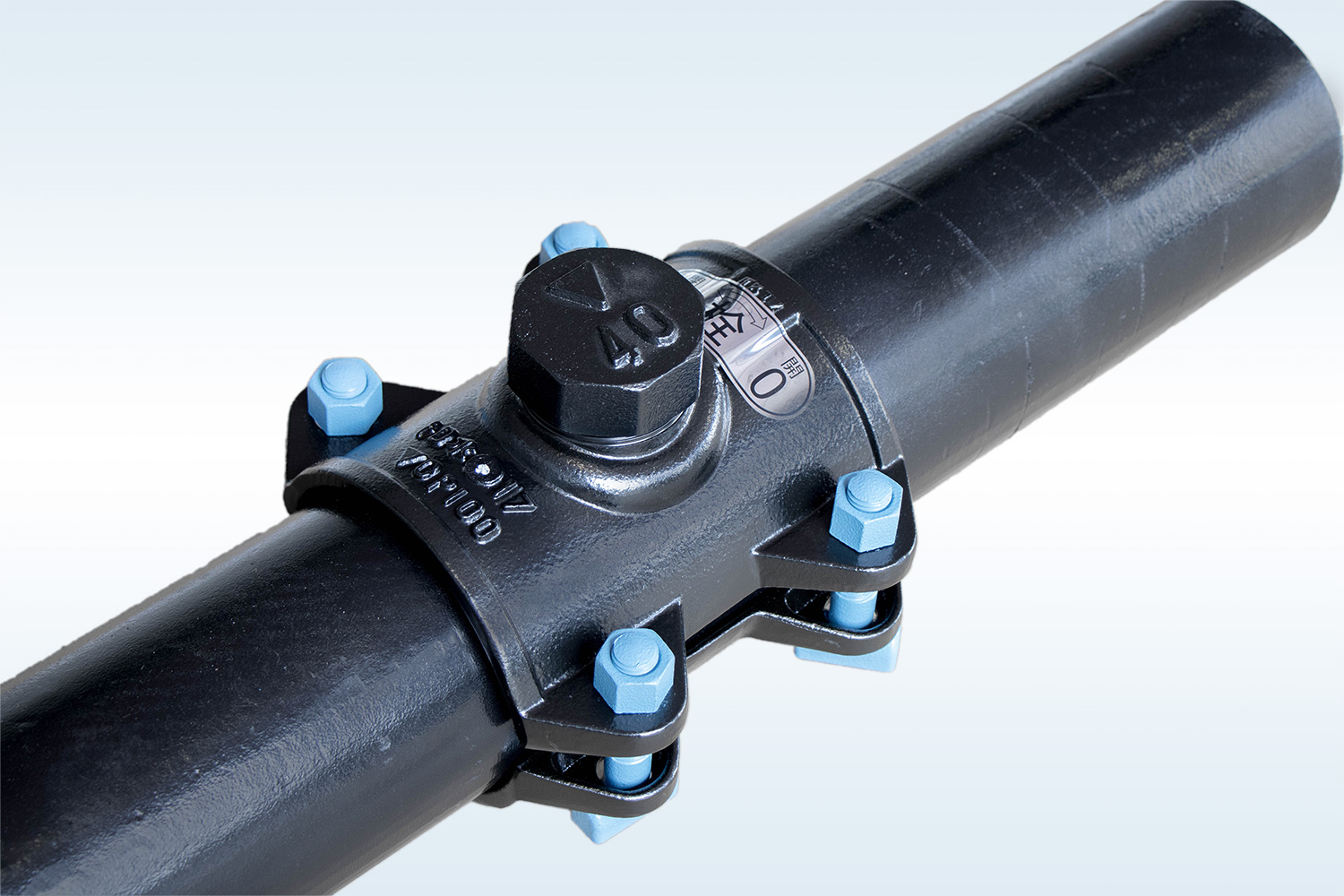
STOPPER SADDLE
STOPPER SADDLE DESIGNED FOR ABS METHOD
FEATURES
FEATURES OF THE STOPPER SADDLE
The stopper saddle is specifically designed and developed for the ABS Method.
Small protrusions/ The protrusions of the saddle is at its minimal size. Less chance of damaging when re-digging.
Anti-corrosive at hole portion/ Plug gasket will adhesively contact to the hole portion. Hence, it will prevent the chance of corrosion。
Reinforcement of ACP/ As the saddle is widely designed, inner circumferential saddle gasket further protects the pipe.
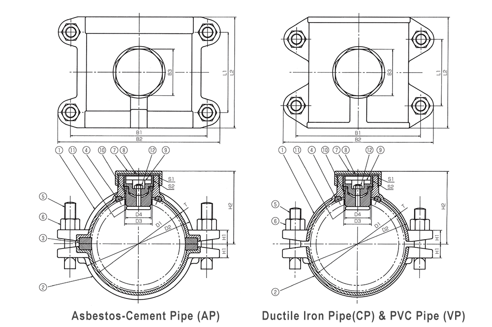
| No. | 1 | 2 | 3 | 4 | 5 | 6 | 7 | 8 | 9 | 10 | 11 | 12 |
|---|
| ELEMENT NAME | Saddle | Band | Saddle Gasket | Hole Gasket | T-Slot Bolt | Nut | Cover | Cover Gasket | Plug | Plug Gasket | Plug Holder | Plug Nut |
| MATERIAL | FCD 450-10 | FCD 450-10 | SBR | SBR | Alloy Ductile Iron | Alloy Ductile Iron | FCD 450-10 | SBR | Alloy Ductile Iron | SBR | Alloy Ductile Iron | SUS 304 |